Piping Application

A Custom Piping CAD Application
Our custom piping CAD application demonstrates how to build a minimal yet powerful CAD solution on top of our WASM-based CAD engine. The full source code is available in our starter repository:
👉 https://github.com/awv-informatik/buerli-starter
This example highlights three key dimensions of CAD customization:
- Interface customization via a simple tabular input
- Guided workflows enforced through clear Add / Edit / Delete actions
- Separated model and geometry logic, fully defined in Buerligons.io
This approach makes it easy to build domain-specific CAD applications without exposing unnecessary complexity to the end user.
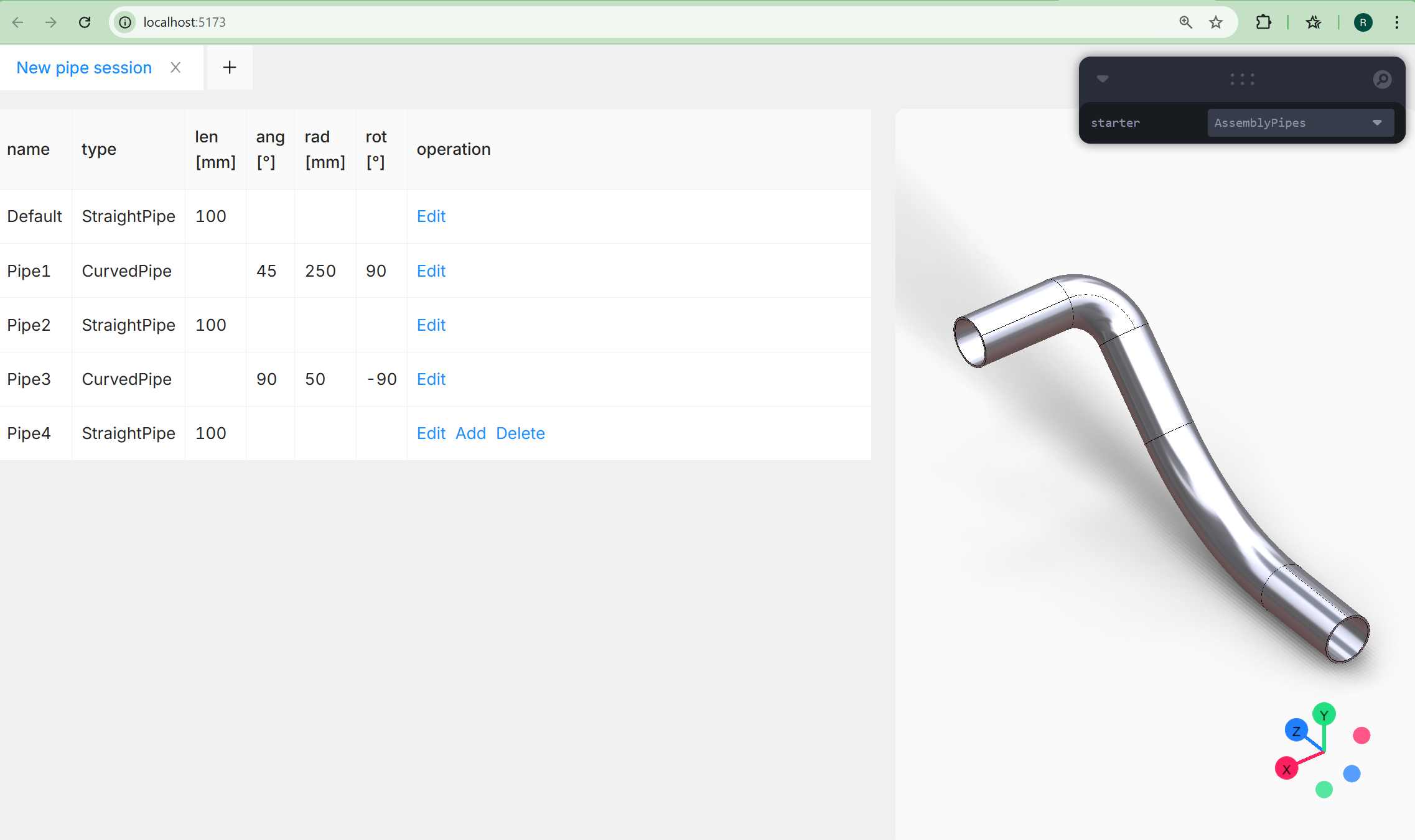
How the Piping Application Works
The example application focuses on a simple yet realistic piping workflow. The model consists of just two parametric part types: Straight pipes and Curved pipes. You start with a straight pipe and then alternately add curved and straight sections to build a continuous pipeline. Each pipe section is fully configurable:
- Straight pipe
- Length
- Curved pipe
- Angle
- Radius
- Rotation
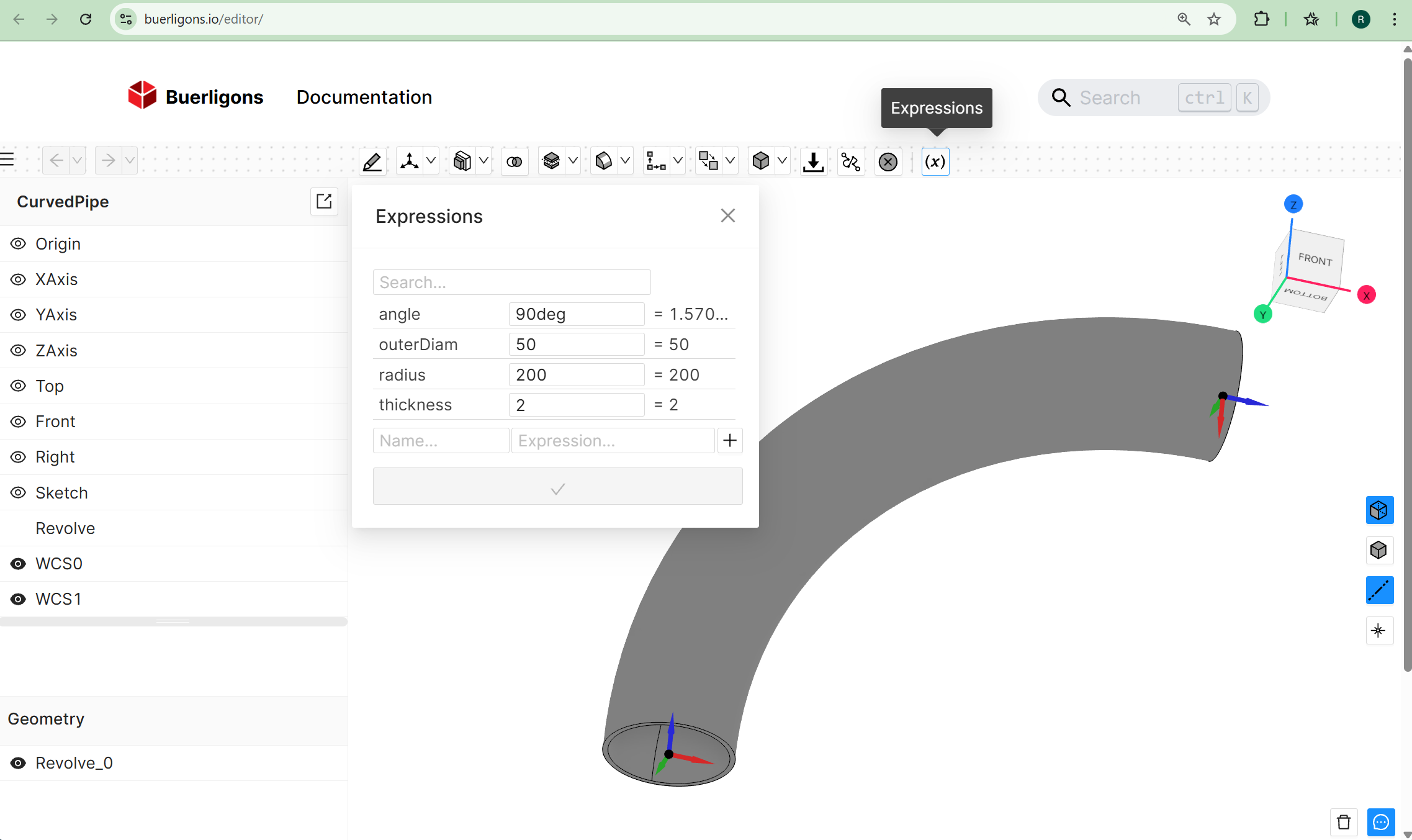
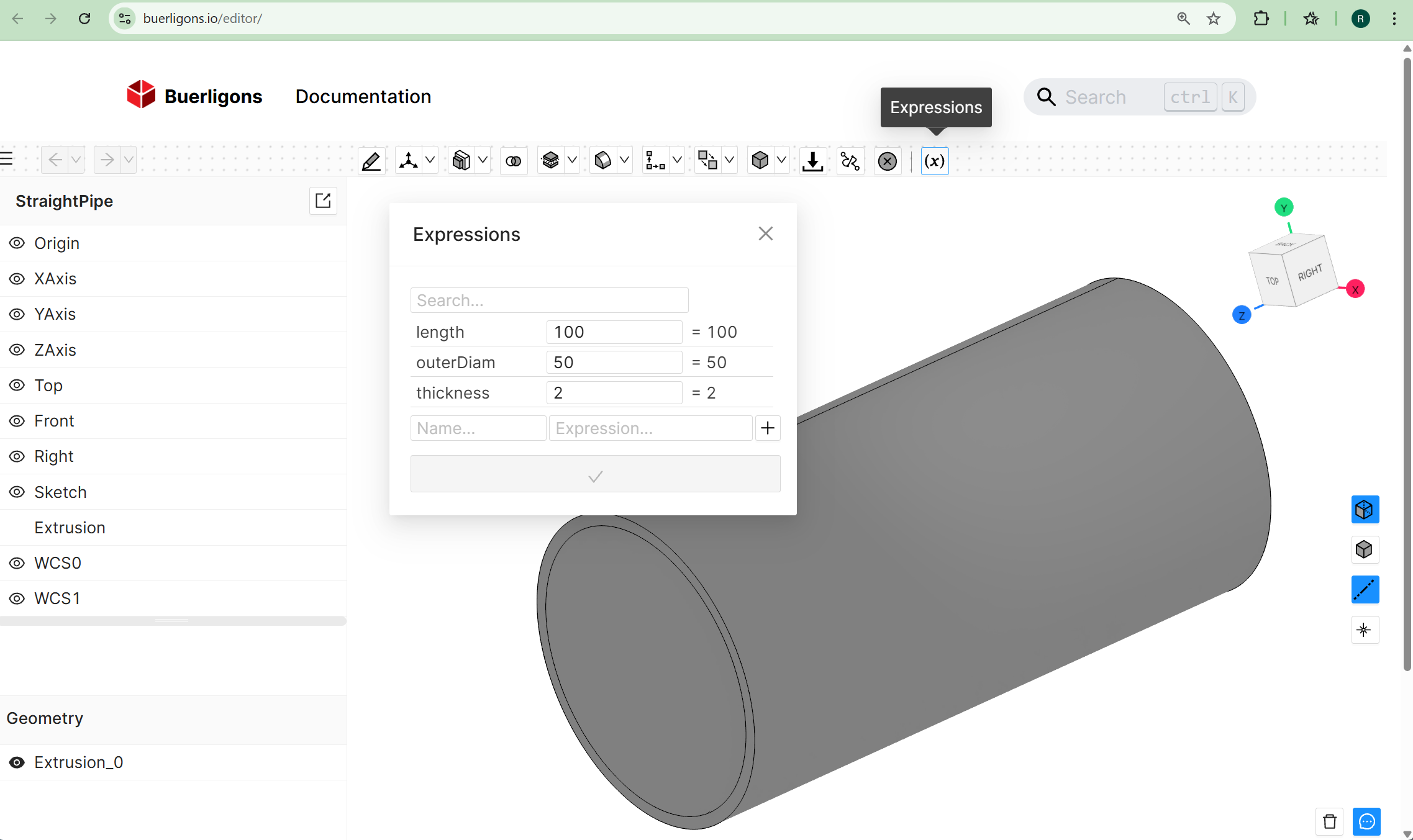
All parts are modeled parametrically within https://buerligons.io our interactive CAD system. You can explore the underlying models by loading them from the repository’s resources folder. The models use:
- Expressions in sketches
- Extrusion features
- Revolve features
These expressions drive the geometry and ensure that parameter changes propagate cleanly through the model. If you’re not yet familiar with expressions in Buerligons, see the documentation: https://buerligons.io/docs/Expressions
Assembling the Pipe System
After configuring individual parts, they are assembled programmatically using the Assembly API. The workflow includes:
- Creating an assembly
api.assembly.create({ name: 'PipesAssembly' }) - Loading pipe part definitions
api.assembly.loadProduct() - adapt part parameter
api.part.updateExpression() - Creating instances of each part
api.assembly.instance() - Positioning them using 3D constraints
api.assembly.fastened()
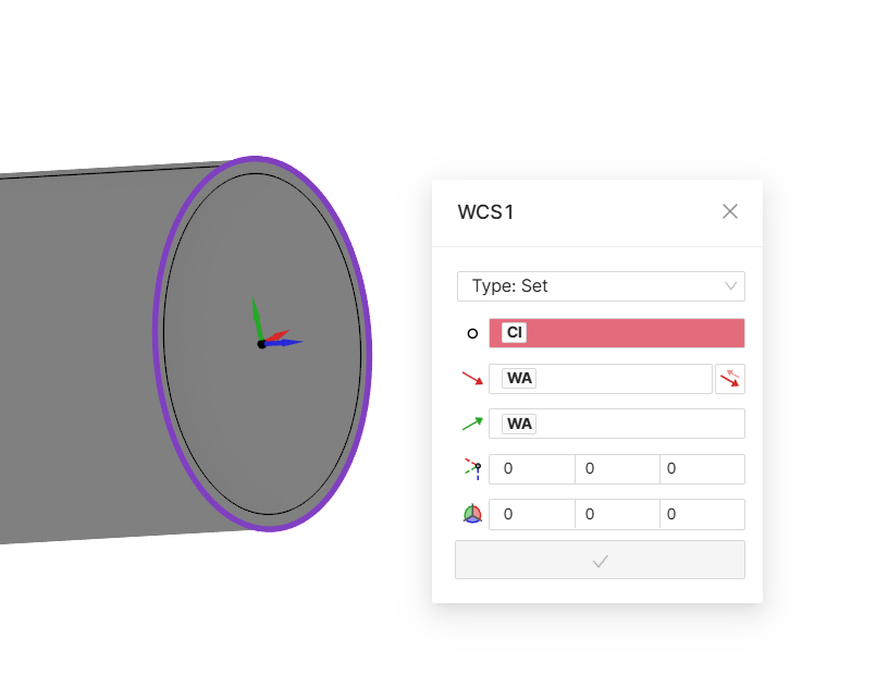
In this example, a fastened constraint is used, where the zRotation parameter is applied to correctly orient curved pipe segments. The mates required for the constraints are simply parametric coordinate systems defined within Buerligons. The origin of WCS1 is defined by referencing a circular B-Rep edge of a revolved solid.
A key advantage of this setup is that any parameter can be edited later in the model history, and the entire assembly adapts automatically and correctly.
Multiple Sessions
A single ClassCAD instance supports multiple sessions, allowing you to switch between them effortlessly. Click the “+” button to create a new session at any time. Each session maintains its own state, making it easy to explore different configurations or workflows. For more details, please refer to the BuerliCADFacade documentation and the related drawing parameters: https://buerli.io/docs/api/classcad#buerlicadfacade
Deploying Your Own CAD App
You can embed your custom CAD application directly on your homepage using our WASM CAD engine. Make sure to configure the allowed origins for your ClassCAD key accordingly. Please refer to the WASM deployment instructions for more details.
Try It Yourself in the Browser 🚀
You can run the complete workflow directly in the browser using WASM—no CAD installation required. ⏳ The first load may take a moment, but subsequent runs are fast and smooth.
Getting Started git clone https://github.com/awv-informatik/buerli-starter
Follow the README to verify the required Node.js version
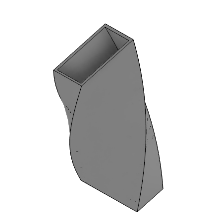
Once running, you’ll have a fully functional, domain-specific CAD application available locally in your browser. I am curious how long it would take for someone to create such an application with rectangular curved, straight and twisted pipes.